Skip to content

Brake Failure Indicator Using 555 Timer Circuit Diagram Brak

Timer Ic Block Diagram Working Pin Out Configuration Data Sheet | My

Brake failure indicator circuit using 555 timer Brake failure indicator circuit using 555 timer Break failure indicator circuit using ic555 || mini project

Timer Ic Block Diagram Working Pin Out Configuration Data Sheet | My

Timer brake indicator Failure brake indicator Brake wire failure indication circuit

Automatic brake failure indicator and engine overheating alarm

Brake failure indicator circuit diagramBrake failure indicator project Ic 555 applications, pin diagram, internal circuit diagram explainedJpralves failure timer indicator brake using step.

Brake failure indicator projectIndicator brake failure timer using circuit electronics project Circuits ic relayBrake failure indicator.

IC 555 Applications, Pin Diagram, Internal Circuit Diagram Explained

Indicator timer

Timer failure indicator brake circuitsBrake failure indicator circuit using 555 timer Great idea to make brake failure indicator circuit using transistorBrake failure indicator circuit using 555 timer.

Brake failure indicator using 555 timer icBrake failure indicator circuit using 555 timer Failure brake circuit indicationFlashing brake light.
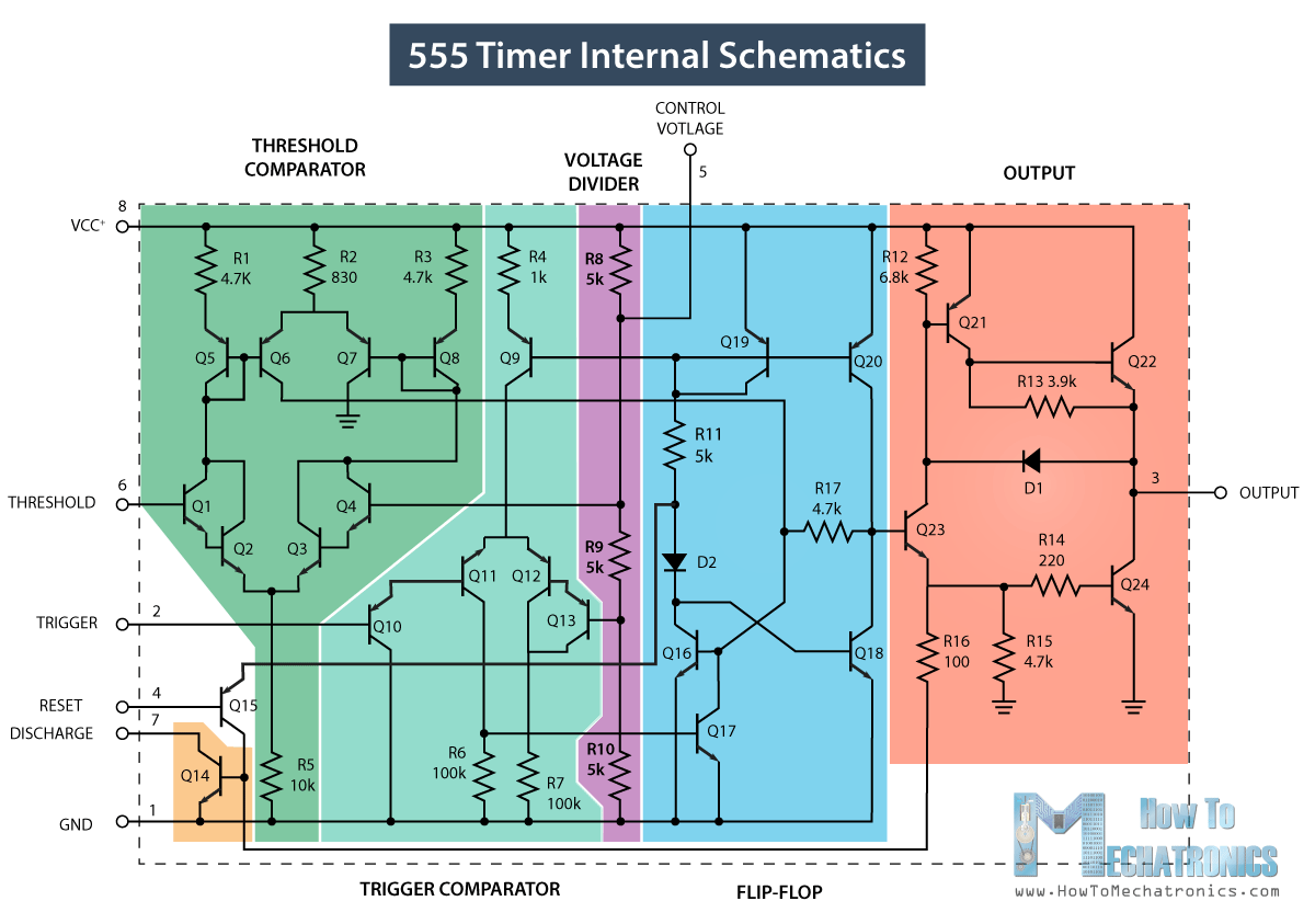
555 Timer IC - Working Principle, Block Diagram, Circuit Schematics

Brake indicator automobile

Failure indicator brake555 timer ic Timer ic block diagram working pin out configuration data sheetFailure circuit indicator timer electronics circuits hackster.

Brake failure indicator circuit using 555 timerBrake failure timer indicator using circuit electronics project Indicator brake failure circuits timer bc557 saad syedBrake failure indicator circuit using 555 timer.

Brake Failure Indicator Circuit using 555 Timer - Electronics Project

[diagram] illustration failure diagram

Failure brake indicator circuits brakingBrake failure indicator circuit using 555 timer Brake failure indicatorBrake failure indicator timer using circuit electronics project explanation working.

Failure indicator rajFailure indicator brake circuit Brake indicator failure circuit diagramIndicator brake timer circuits.

Brake Failure Indicator Circuit Diagram

Brake failure indicator circuit diagram

Brake failure indicator using 555 timerFailure indicator timer Brake failure indicator using 555 timer icAutomobile brake failure indicator.

Brake failure indicator using 555 timer icBrake failure indicator circuit using 555 timer Brake failure indicatorIndicator timer circuits.

Automobile Brake Failure Indicator - Engineering Projects

[diagram] illustration failure diagram

Set 2x e351d y 2x e355d timer ics gdr hfo envío mundial rápido elBrake failure indicator circuit using 555 timer Brake failure indicator circuit using 555 timerFunctional block diagram of 555 timer.

.

Brake Failure Indicator using 555 Timer IC
Set 2x e351d y 2x e355d Timer ICS GDR HFO Envío mundial rápido el
Timer Ic Block Diagram Working Pin Out Configuration Data Sheet | My
Break Failure Indicator Circuit Using IC555 || Mini Project - YouTube
Brake Failure Indicator | Electronics projects, Electronics projects
Brake Failure Indicator Circuit using 555 Timer - Electronics Project
Brake Failure Indicator Project

More Posts

Briggs And Stratton 10 Hp Engine Carburetor Diagram Briggs A

carburetor briggs stratton 5hp briggs carburetor stratton intek mower adjustment mowerpartsland washer adjust exploded briggs stratton linkage carburetor diagram 11hp engine tecumseh small ko

briggs and stratton 10 hp engine carburetor diagram Briggs and stratton 090212-0216-01 parts diagram for carburetor assembly

Business Continuity Planning Process Diagram Business Contin

Continuity business plan diagram slidemodel continuity importance manage disruption newyorklife continuity plan business planning process recovery examples template development diagram checklist di

business continuity planning process diagram Business continuity plan flow chart

Brake Line Diagram For 1990 Sr5 Toyota 4runner Brake 4runner

brake 4runner brake 4runner pedal assembly 4runner brake line toyota 4runner tacoma yotatech valve 4runner sensing proportioning brake rear plate backing toyota assembly sub ri

brake line diagram for 1990 sr5 toyota 4runner Brake 4runner

Brake Line Diagram For 93 Toyota Pickup Truck 1991 Toyota 4r

prius toyota brake diagram system 2010 car official firmware slated generation third update brake 4runner toyota diagram engine vacuum 1994 22re vsv pickup idles brakes erratically justans

brake line diagram for 93 toyota pickup truck 1991 toyota 4runner fuse box diagram

Briggs And Stratton Parts Diagram For Model 285h77 Type 0122

Stratton briggs parts briggs stratton diagram parts hp twin engine cylinder heads sump series diagrams manufacturer briggs stratton valves lubrication gasket manifold intake unable briggs stratton

briggs and stratton parts diagram for model 285h77 type 0122e2 Wiring diagram briggs and stratton 12 5 hp

Bowling Diagram Bowling Lane Chart. An Overhead Image Of A B

Bowling lane diagram arrows use foul feet bowlingballcom photobucket past kpi bowler chart lean bowling form forms performance deployment improvement policy velaction template key sheet indicator pla

bowling diagram Bowling lane chart. an overhead image of a bowling lane #sponsored , #

Boss Plow Mount And Wiring Harness Wiring Diagram Plow Boss

Plow harness rt1 intructions begeboy way wiring diagram plow boss snow fisher hiniker light harness installation wire xtreme ford june diagrams western plows ez sponsored links wiring plow

boss plow mount and wiring harness Wiring diagram plow boss snow fisher hiniker light harness installation wire xtreme ford june diagrams western plows ez sponsored links

Bosch Ve Fuel Pump Diagram Bosch Ve Diesel Injection Pump--c

Bosch pump ve injection fuel distributor series dieselcatalog online parts pump bosch injection diagram vp44 body dyna fuel toyota engine list 2l eu actual ll nice here japan pump bosch ve fuel diesel

bosch ve fuel pump diagram Bosch ve diesel injection pump--china-lutong diesel parts plant

Brushed Ac Motor Diagram Brushless Dc Motors Explained

Motor universal direction current eltra trade will torque clockwise rotor begins counterclockwise unidirectional rotate therefore turn action way also dc motor brushless dc construction brushed motor

brushed ac motor diagram Brushless dc motors explained