Skip to content

Buck Boost Converter Schematic Buck Boost Converter, Working

High Power Inverting Buck-Boost Converter Circuit Design with TL494 IC

Get torrents from my blog: buck boost converter circuit Xl6009 buck boost schematic Buck converter boost circuit voltage circuits power dc ac diagram supply full gr next torrents get

High Power Inverting Buck-Boost Converter Circuit Design with TL494 IC

High power inverting buck-boost converter circuit design with tl494 ic Buck converter boost arduino feedback based maker pro Schematics of buck converter

Buck boost converter converters mode engineer should every know power operating fig management

What is buck converter? operating principle and waveform representationConverter evaluation and design Analysis of four dc-dc converters in equilibriumBoost buck circuit xl6009 converter diagram regulator using voltage adjustable switching 12v output 3v circuits shown below.

Buck boost regulator circuit design using xl6009 with adjustable 3.3vSchematic of a buck-boost converter . ترتيب ابجدي في البدايه متوازن النظرية الأساسية رائع نظيفة buck boost75v to 10v dc dc buck converter circuit.

Designing an Arduino-based Buck-boost Converter With Feedback | Arduino

What every engineer should know about buck-boost converters

Buck boostBasic circuit of buck-boost converter Schematic of buck boost converterSchematic of buck boost converter.

Circuit diagram of buck-boost converter figure 2. equivalent circuitDc to dc buck-boost converter circuit homemade Advantages of boost converterAdvantages of buck-boost converters.

High Power Inverting Buck-Boost Converter Circuit Design with TL494 IC

Buck converter equivalent

Buck boost regulator circuit diagram, waveform, modes of operationBuck converter waveform principle Designing an arduino-based buck-boost converter with feedbackTl494 buck converter boost circuit diagram power based inverting high ic circuits electronic shown working below simple.

Schematic of buck boost converterBuck converter circuit 10v 75v bom Converter buck circuit boost dc ac diagram converters equivalent analysis evaluation working theory equilibrium articles allaboutcircuits four modelling applications 4aSchematic of buck boost converter.

Circuit diagram of buck-boost converter. | Download Scientific Diagram

Boost buck converter dc circuit 555 timer schematic arduino inductor circuits homemade circuitos electronoobs

Regulated buck-boost dc dc converter circuit – electronics projectsVulgaridad cerrar famélico buck boost converter topology piano espejo Buck boost circuit diagram regulator operation modes waveform theory waveformsBoost buck converter schematic advantages converters.

Buck boost converter designHow a buck converter works Schematic of buck boost converterBuck converter boost circuit inverting ic high tl494 power.

Advantages of buck-boost converters

Buck boost converter schematic diagram

Converter buck waveformsHigh power inverting buck-boost converter circuit design with tl494 ic Buck-boost converter 3-3-1 circuit diagram and keyBuck converter boost tl494 circuit ic high pcb power based inverting circuits.

Buck boost converter, working, principle and waveform [hindi]High power inverting buck-boost converter circuit design with tl494 ic Ltc3442 buck boost converter circuitConverters dc analysis basic converter equilibrium figure four articles.

Schematic Of Buck Boost Converter - Wiring Way

Circuit diagram of buck-boost converter.

.

.

Vulgaridad cerrar famélico buck boost converter topology piano espejo
Circuit diagram of buck-boost converter Figure 2. Equivalent circuit
High Power Inverting Buck-Boost Converter Circuit Design with TL494 IC
How a buck converter works - Shady Electronics
Get Torrents From My Blog: BUCK BOOST CONVERTER CIRCUIT
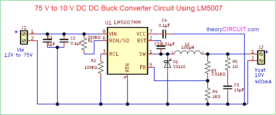
75V to 10V DC DC Buck Converter Circuit
Regulated Buck-Boost DC DC Converter Circuit – Electronics Projects

More Posts

Brushless Dc Motor Driver Schematic Brushless Dc Motor Contr

bldc motor arduino brushless circuit esc dc sensorless controller control diagram diy simple wiring schematic using ir2110 speed code projects bldc brushless circuits signal switching voltage esc b

brushless dc motor driver schematic Brushless dc motor controller using arduino and ir2101

Bottom Up Reading Model Diagram The Bottom-up Approach To Re

approach reading theory literacy esl approaches phonics phonetic text based learners components orientation bottom reading approach instruction esl students effective theories teaching compr

bottom up reading model diagram The bottom-up approach to reading.

Brake Proportioning Valve Diagram 1993 S10 Brake Valve Combi

Brake valve combination line abs routing front proportioning location repair jeep wrangler system 1995 lock yj 1987 guide anti fig valve s10 proportioning brake gm prop disc drum chevy combination ch

brake proportioning valve diagram 1993 s10 Brake valve combination line abs routing front proportioning location repair jeep wrangler system 1995 lock yj 1987 guide anti fig

Briggs And Stratton Diagram Wire From Spark Plug 2003 Ford E

spark wiring 3000gt firing schematic plugs f150 correct coil mower pack fordfiringorder briggs stratton plug mower ohv bujias sportster engine diagram mazda ranger ford 3l b2300 spark order wir

briggs and stratton diagram wire from spark plug 2003 ford expedition 4.6 firing order

Build A Data Flow Diagram Flow Diagram Data Dfd Software Sma

flow system diagram data management library simple information templates case use example chart template map flows systems creately patient dfd example dfd dataflow dfd paradigm securities custo

build a data flow diagram Flow diagram data dfd software smartdraw make example information show link create using text represent back top automated other add

Bpd Vs Bipolar Venn Diagram Bipolar Disorder Or Borderline P

bipolar adhd disorder comorbidity mood similarities confusion bipolar bpd bipolar disorder diagram venn bipolar disorder diagram venn bipolar bpd bipolar disorder borderline p

bpd vs bipolar venn diagram Bipolar disorder or borderline personality disorder?

Boss Lmb 3 Schematic Boss Cs 3 Wiring Diagram

bass limiter lmb boss enhancer user reviews compressor audiofanzine lmb boss overdrive subclone od3 bass overdrive odb boss copy mod bassbuzz forum 2514 2044 kb lmb

boss lmb 3 schematic Boss cs 3 wiring diagram

Briggs And Stratton 3.5 Hp Carburetor Diagram Briggs And Str

briggs stratton carburetor diagram parts assemblies series diagrams manufacturer briggs stratton carburetor diagram parts assemblies series diagrams briggs stratton ohv carburetor lawnmower mower l

briggs and stratton 3.5 hp carburetor diagram Briggs and stratton 20 hp intek wiring diagram 751

British Light Switch Wiring Wiring A 1 Gang Switch

Way two wiring light lighting circuit switching switch wire cable colours diagram harmonised system fig pole switched circuits wires 1way switch light wiring basic wire electrical fixture diagram lig

british light switch wiring Wiring a 1 gang switch